


|
|
Digital Hydraulics Help To Position Railway Bridge 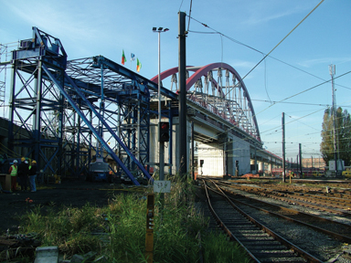
Irene Kremer, Enerpac
BV,
Local conditions sometimes make it impossible to build a bridge on-site. In those cases, the bridge must be built up on an adjacent site or bank and then moved to the final position. This is what happened in the Brussels Schaerbeke, where a steel railway bridge with a length of 140 m and a weight of over 1600 t had to be slid across a number of already existing tracks. Enerpac was asked to hydraulically monitor the movement and the forces that occurred during the movement with its digital 'Synchronous Lifting System' and to make corrections if necessary. The new railway bridge in Brussels was built by order of the Belgian railways by Victor Buyck Steel Construction, a large internationally operating Belgian steel construction company. The bridge was supplied in parts and assembled on one side of the newly built railway viaduct. Because of the intensive use of the railways over which the bridge had to be placed and the fact that the railway traffic had to be stopped during the movement, the builder was given only 48 hours to move the bridge to its proper place.
In order to have the combined action of forces develop evenly during the movement of the railway bridge and to prevent these tensions from becoming too high, the occurring pulling and pushing forces had to be measured and reduced if required. Additionally, the vertical position of the bridge had to be monitored, of course. Manual monitoring and correction of the movement is too inaccurate in these cases. To much variation at the different points of support results in unacceptable tensions that may affect the construction. Besides, manual monitoring and correction takes much time and the builders did not have much time. Therefore Enerpac was asked to guide the movement of the railway bridge with its 'Synchronous Lifting System' that had already proven itself all over the world.
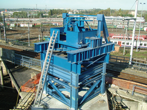
Eight temporary steel pillars were built to support the viaduct parts during the movement. Each pillar had been provided with a so-called 'draw beam', a pivoting steel cross with heavy springs to compensate the force, the angular displacement and the bending of the lower beam of the bridge. Beneath each 'draw beam' two hydraulic cylinders were mounted. The primary function of these cylinders was to keep the construction at the correct height. In order to reduce the resistance as much as possible during the movement Teflon gliding plates were applied between the 'draw beam' and the lower beam.
Forces under control
Synchronous Lifting System: Digital hydraulics
The computer continuously calculates the force on each cylinder using pressure sensors. The system checks the position and movements of the individual cylinders and controls pump and valves if necessary to keep the forces at the correct value. In this way each point of the object is moved automatically and fully synchronically and positioned with millimeter accuracy. When the force is outside a set value, the pressure is 'adjusted'. Here the speed of the computer is used to quickly send short pulses to the hydraulic valves. The result of this is that the individual cylinder movements can be many times smaller than with manual operation. At the moment that a cylinder movement is outside the tolerance, a warning signal is sent and the entire movement is stopped manually or automatically.
|
|
© InfraStructures - Tous droits réservés - All rights reserved |
 Complex combined action of forces
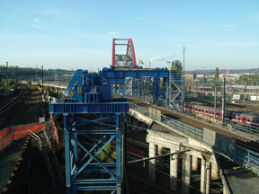 Platform wagons and strand-jacks
 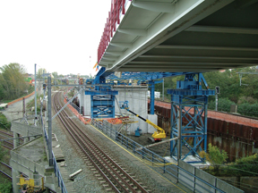 Additionally, a launching nose (beak) was provided on the front side
of the bridge for a safer distribution of the forces and to limit the bends
and tensions during the movement.
Additionally, a launching nose (beak) was provided on the front side
of the bridge for a safer distribution of the forces and to limit the bends
and tensions during the movement. 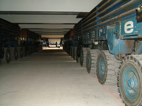 Both the hydraulics and the electronics of the system were designed and
developed by a team of experts in the 'Enerpac Center of Excellence' in
Spain. Enerpac itself hired out the equipment to the client, in accordance
with the policy pursued with respect to such large projects. The installation
and implementation were taken care of by the so-called Heavy Lift Team,
experienced Enerpac experts from Great-Britain. The total project period
- installation phase, test phase, implementation and completion - covered
two weeks.
Both the hydraulics and the electronics of the system were designed and
developed by a team of experts in the 'Enerpac Center of Excellence' in
Spain. Enerpac itself hired out the equipment to the client, in accordance
with the policy pursued with respect to such large projects. The installation
and implementation were taken care of by the so-called Heavy Lift Team,
experienced Enerpac experts from Great-Britain. The total project period
- installation phase, test phase, implementation and completion - covered
two weeks. 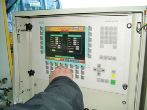 The total system is built in such a way, that the different measuring
points and cylinders are stable and do not influence each other and it checks
the measuring way and force. For this the control system receives electronic
signals from the movement sensors and the pressure in the cylinders is also
electronically transmitted through sensors.
The total system is built in such a way, that the different measuring
points and cylinders are stable and do not influence each other and it checks
the measuring way and force. For this the control system receives electronic
signals from the movement sensors and the pressure in the cylinders is also
electronically transmitted through sensors.


