The Pump, the Heart of Any Hydraulic System
Richard hacker,
ACE Accent Electronic Controls Inc.
Special Collaboration
For decades trucks have used hydraulic systems to operate auxilliary equipment. In that time technology has advanced significantly. The following is a review of the primary components and principles used in the design, installation and maintenance of portable hydraulic power systems.
Hydraulic system functions
A winter maintenance truck with plow, wing and spreader has very varied demands for the hydraulic system.
The spreader can work continuously, 24/7 in some conditions, with hydraulic flow (Q) between 7.5 and 20 l/min, with pressures (P) between 27.5 and 125 bar.
The plow operates intermittently with long inactive periods and requires 40-60 l/cycle, with pressures approaching 70 bar.
Many functions must operate simultaneously without interfering with the operation of the other equipment. This is further complicated by vehicle speed, drivetrain configurations and other equipment that may be fitted but is not germain to the snow operations.
Hydraulic pump location
Typically pump location is a secondary consideration as most American chassis makers give little thought to auxilliary equipment when designing bodywork and drivetrains. This has seen most pump installations being front-mounted with direct crankshaft drive. This puts severe strain on the pump as it is often a considerable length from the oil reservoir, mounted higher than reservoir level and must start/stop every time the truck engine does, often while under a hydraulic load. It also affects the operator’s visibility as it can add several feet to the front of the vehicle.
The rise of severe duty automatic transmissions for over the road use like the Allison 3000 and 4000 Series, has created other mounting options.
Cab-over chassis also offer the possibility of back of cab mounts and auxilliary drives, available for most diesel engines, can permit some pumps to be located under the hood.
The criteria for mounting however should conform to “Best Practices” for hydraulic system design. Chiefly:
- reduce hose lengths where possible, particularly suction line
- maintain positive head pressure at the pump inlet
- ease of service
- radiant cooling
- protect components from abuse and damage
Possible Hydraulic Circuit Configurations
A) Tandem fixed-displacement (spur gear) pump, with separate valves for the spreader and plows. These may also have a third valve for flow summation to permit the operation of a body hoist or other auxilliary machinery.
B) Single fixed-displacement pump and multi-section control valve. The flow rating (Q) for this pump will be marginally greater than that found in option A).
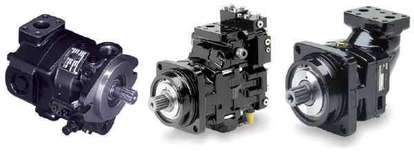
C) A variable displacement pump with hydraulic or electronic displacement control. This is the standard for most mobile hydraulic equipment such as excavators. The displacement control permits the incremental control of circuit flow (Q) improving efficiency, fuel economy, system life and reducing heat and wear of the pump. This configuration is often referred to as “Load Sensing”.

Which System To Chose
A) At present this is the most common configuration found on Canadian winter maintenance vehicles. It is one of the oldest and most basic hydraulic pump configurations which is also reflected by the low cost. However cost and simplicity are not always straightforward when dynamic hydraulic systems are concerned.
Variations of input RPM will create surges in flow (Q) and pressure (P) that affect the smooth and efficient operation of spreaders and other equipment. The constant rotation increases pump wear and increase heat as oil circulates through restrictions even when equipment is idle. This increased heat is often unable to be dissipated as typically the hydraulic oil reservoir has been significantly undersized to save space and cost. This is often most notable at the start and end of the winter maintenance season.
B) A single fixed-displacement pump will suffer from most of the same problems as the tandem version. As the displacement tends to be larger the issue of heat is often identified much sooner than in the tandem arrangement. Again input RPM will create surges affecting the correct operation of plows and spreaders. If cost and chassis layout are the main considerations for choosing this type of hydraulic pump then attention to reservoir capacity and general circuit layout is important.
C) A variable displacement pump does not suffer from any of these limitations. It is possible to combine just about any size of pump with any size of valves, without major problems. Associated with load sensing valves the pump moves oil on demand only. This gives excellent flow at low engine RPM while having speed and precision according to function needs.
Reservoir size and inlet head pressure are very important to ensure efficiency and long pump life. Filtration and oil condition are also of a higher importance than is typical with the other systems.
Although the upfront cost is higher, the reliability and efficiency contribute directly to the effective operation of the equipment and when correctly installed and maintained tend to enjoy much longer service lives than the rest.
It is important to remember that the pump is only one part of a complete hydraulic system integrating various other components. Defining the functions and performances that are required is the primary task before spending time and money on system design and componentry.
Conclusion
The pump is more than a simple accessory, it is the heart of the hydraulic system. Its choice will determine to a large extent the performance and efficiency of the truck and equipment. A vendor may propose solutions according to criteria that may not necessarily be those of the customer. When in doubt seek out the assistance of a recognized hydraulic technologist, usually someone with forestry or construction equipment experience or consult a CFPS (Certified Fluid Power Specialist). |


